Driving a high-quality LED strip with ESPHome and ESP32-C3
It’s been over a year since I’ve taken on a new LED strip project. This is probably because of the rock-solid reliability demonstrated by the strips I already have installed. These are the “individually-addressable” style of strip, with RGBW colour. I drive them with the WLED firmware running on the excellent ESP8266 control boards from ElectroDragon (I’ve written about these boards before).
Colour strips are great for decoration, but there are better options for illuminating a room with high-quality light. I stumbled upon some nice temperature-adjustable white LED strips on AliExpress recently. Unlike individually-addressable strips where control is done via a signal line, these strips are what I like to call “direct drive”, where the input voltage is applied directly to the LED strip and brightness is changed via current control or PWM.
ESP8266 boards aren’t ideally suited to driving these strips directly because their PWM implementation is in software, not hardware. This can cause flickering. But I was recently overjoyed to notice ElectroDragon is now selling an ESP32-based version of the driver board. The ESP32 has the notable benefit of hardware PWM—perfect for LED strips that require direct voltage!
Armed with this knowledge and a bunch of components, I set out to install my new temperature-adjustable ceiling light.
Hardware
The LED strip
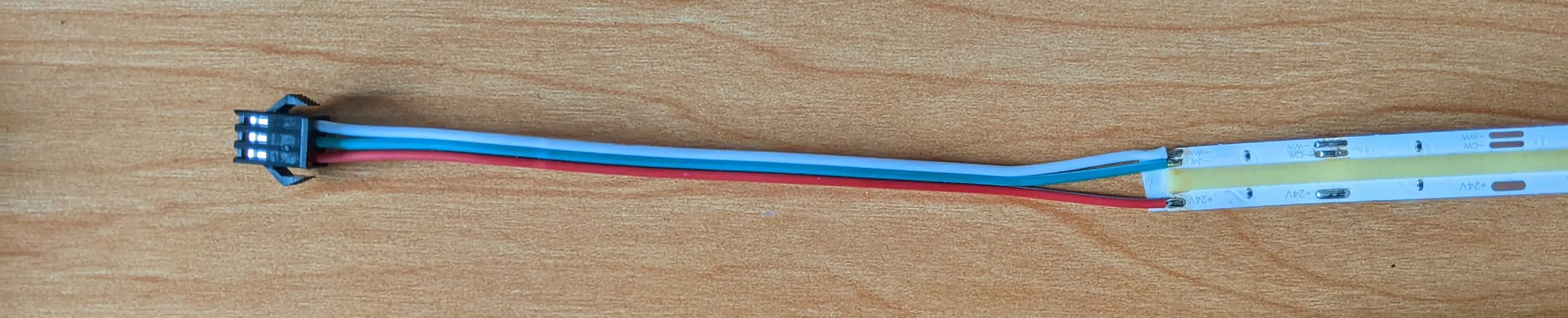
I’m using a 24V two-channel white COB LED strip. One channel is warm white, and one channel is cold white. I went with this strip for a few reasons:
- This is for ceiling lighting; I don’t need colour and I don’t need individually-addressable LEDs.
- I enjoy the idea of having controllable colour temperature so I can change it during the day or connect it to Flux for automatic temperature changing over the course of the day.
- The CRI of these strips is excellent at Ra>90. For comparison: the white channel of my colour SK6812 strips is generally rated at Ra>70. This all means the COB strip gives off a much fuller-feeling light that is more suitable to illuminate a room.
- 24V is a high enough voltage that I can run over two metres of the strip without having to wire up extra power lines to intermediate points along the strip (something I had to do with my 5V addressable strips).
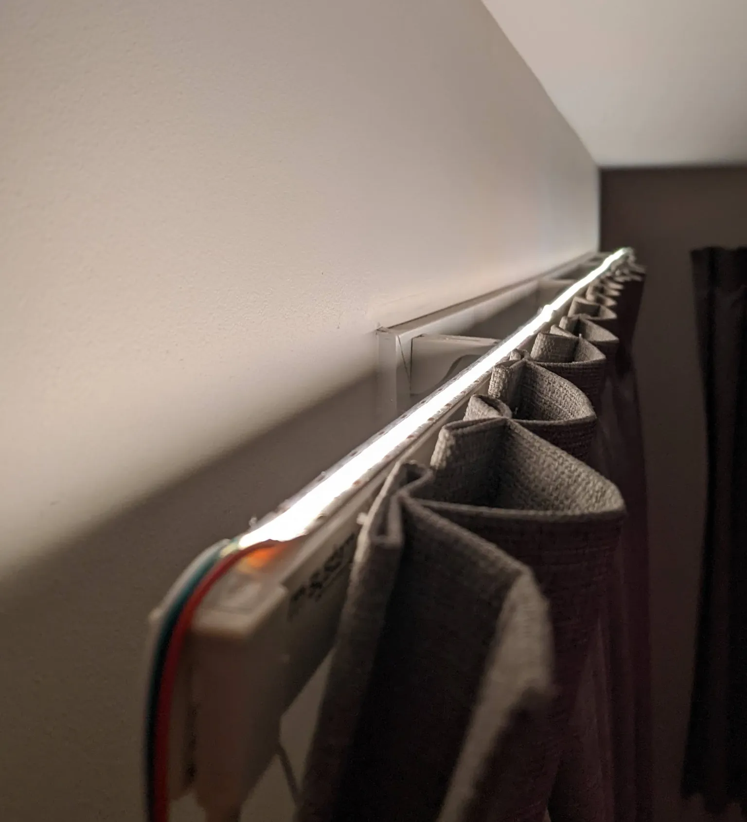
- The COB (chip on board) design of this particular strip is incredibly bright at over 700 lumens per metre.
- With an insane 640 LEDs per metre, the strip basically has all the diffusion it needs built right in. This is less of a concern given I will be bouncing the light off the ceiling.
You’ll need a 24V power supply to use with these. I bought a cheap supply from BTF Lighting, the same seller as the LED strip. I would recommend a more reputable 24V supply, perhaps one of those more traditional “plastic brick” style ones.
The driver
I have loved working with ElectroDragon’s ESP8266 boards in previous projects. It’s a basic LED strip controller with built-in MOSFETs and voltage regulation—configurable to drive addressable LED strips like the SK6812 or “direct” LED strips by sending PWM signals to the MOSFET pins.
A big downside of the ESP8266 is its lack of hardware PWM. This means a direct drive LED strip (like the one I’m using in this project) would be more likely to flicker as the microcontroller juggles PWM signalling, WiFi connection, and other tasks with competing priorities. That’s simply not an issue with the new ESP32 boards. PWM is managed using what are called LEDC channels: just specify a PWM frequency and it will be taken care of in hardware. At 7USD a pop for the upgraded version, more people should know about these delightful boards.
To configure the board’s hardware in this project, I set both power jumpers to the “5-27V” setting. This means that I can use the 24V power supply required for the strip as input and power will be passed straight through. At the output side, I set the jumpers to R (as opposed to GND) and G (as opposed to IO2). This is the configuration for driving those “direct” LED strips via the MOSFETs.
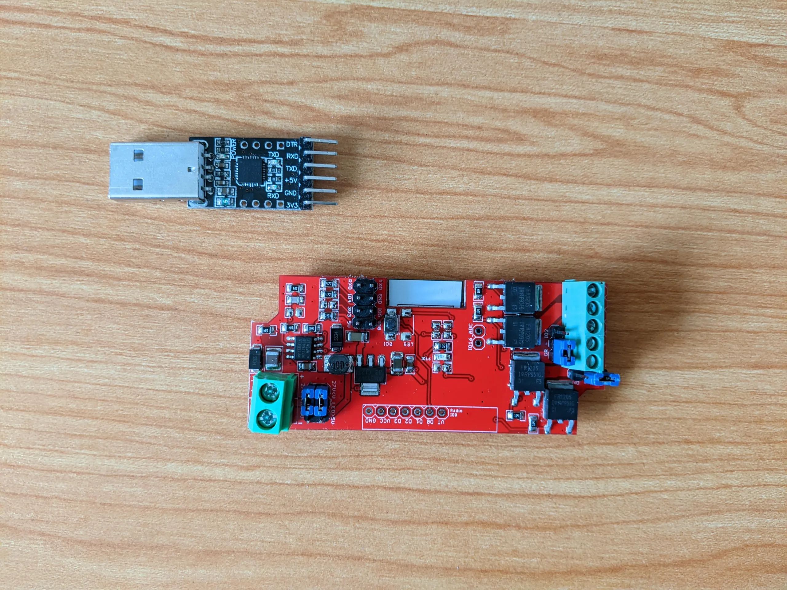
The board comes with screw terminals for the power connections. I was happy to see that unlike previous revisions, the power input terminals are labelled on the silkscreen. Like on my other projects with the board, once I was happy with my configuration, I soldered the input wires, output wires and jumper settings in place.
Software
There are two options here: the flexible ESPHome, or the more LED-focused WLED, which now supports two-channel white strips. I went with ESPHome, mostly because WLED doesn’t have support for ESP32-C3 (read on for more about that) but also because ESPHome has supported this kind of strip for much longer.
The end result I want is a temperature-controllable light entity in Home Assistant. Fortunately, ESPHome has the cwww light platform which is exactly for this application. The ledc output component lets me use that glorious hardware PWM, too.
The configuration I went with looks something like this:
esphome:
  name: ceiling_light
  platformio_options:
    board_build.flash_mode: dio

esp32:
  board: esp32-c3-devkitm-1
  framework:
    type: arduino
    version: latest

wifi:
  ssid: !secret wifi_ssid
  password: !secret wifi_password

  # Enable fallback hotspot (captive portal) in case wifi connection fails
  ap:
    ssid: 'Ceiling Light Fallback Hotspot'
    password: !secret wifi_ap_password

logger:

api:

ota:

light:
  - platform: cwww
    name: 'Ceiling light'
    cold_white: greenpin
    warm_white: redpin
    cold_white_color_temperature: 6000 K
    warm_white_color_temperature: 2700 K # From the strip's datasheet but pretty sure it's more like 3000K in reality
    constant_brightness: true

output:
  - platform: ledc
    pin: GPIO5
    id: greenpin
    frequency: 19531Hz
  - platform: ledc
    pin: GPIO8
    id: redpin
    frequency: 19531Hz
  # - platform: ledc
  #   pin: GPIO4
  #   id: bluepin
  #   frequency: 19531Hz
  # - platform: ledc
  #   pin: GPIO3
  #   id: whitepin
  #   frequency: 19531Hz
There are some important bits in here:
board: esp32-c3-devkitm-1signifies that this isn’t an ESP32 but rather the related-by-name ESP32-C3. The ESP32-C3 is less powerful but contains many of the ESP32’s key features. It’s also much newer than the ESP32 and runs on the completely different RISC-V architecture. The small package size of the ESP32-C3 means it can be used by manufacturers as a drop-in replacement for the ESP8266 on boards like the ElectroDragon one, and I can only see the popularity of this chip skyrocketing.board_build.flash_mode: diois absolutely required for flashing to work successfully. Without this line, the board will default to QIO mode which resulted in boot loops on my ESP32-C3 board.frequency: 19531Hzis taken from the table of recommended frequencies published in the ESPHome documentation. Initially I tried 1220Hz as this results in the most steps available for buttery transitions. Unfortunately, my power supply produced a loud whining sound and some flickering at that frequency. So I switched to the lowest recommended frequency above my hearing limit of about 18kHz; 19.5kHz it was! A worthwhile change for the eliminated flickering and noise—and I don’t notice a difference in transition smoothness. A lower recommended frequency may work well for you if you have a better quality supply.
A note on pins
I’ve included the other pins on the board, commented out, for reference purposes. This took some sleuthing as ElectroDragon originally didn’t publish the pin numbers for the ESP32 variant of this board. Here’s a table of what I found:
| Output channel | Pin (ESP8266 variant) | Pin (ESP32-C3 variant) |
|---|---|---|
| G | GPIO13 | GPIO5 |
| R | GPIO15 | GPIO8 |
| B | GPIO12 | GPIO4 |
| W | GPIO14 | GPIO3 |
| Signal (SK6812 or similar) | GPIO2 | GPIO10 |
Flashing the board
I used the ESPHome dashboard interface to enter and export the config. From the dashboard, find the device you’re flashing and select Install -> Manual download -> Modern format. It should compile and download a bin file which can be flashed to the ESP.
The documentation for “Modern format” is entirely absent but after much pain and learning about bootloaders I can confirm this is the option you want. I believe “modern” generates an image including the bootloader, which makes it really simple to flash to the
0x0offset. “Legacy” exports an image for tools which provide their own bootloader.
Connect the ESP board to a USB FTDI adapter. My FTDI adapter is based on the CP2102 and includes a 3.3V output. Connect GND->GND, RX->TX, TX->RX and 3V3->3V3. The ElectroDragon documentation recommends using 5V->5V instead of 3V3->3V3 (I think this is what I have done on previous projects) but either should work.
I flashed the board on Linux using esptool.
Before each
esptoolcommand, hold down theIO0button on the ESP board while plugging the FTDI adapter into the computer. This signals the ESP to boot in flash mode.
First, erase the contents of the flash:
python -m esptool -p /dev/ttyUSB0 -b 460800 --before default_reset --after hard_reset --chip esp32c3 erase_flash
Now replug the board and flash the firmware:
python -m esptool -p /dev/ttyUSB0 -b 460800 --before default_reset --after hard_reset --chip esp32c3 write_flash 0x0 firmware-factory.bin
Easy as! The device should eventually appear as online in the ESPHome dashboard. Over-the-air flashing will be possible now.
For troubleshooting, I found picocom a useful tool to monitor serial output over USB:
picocom -b 115200 /dev/ttyUSB0
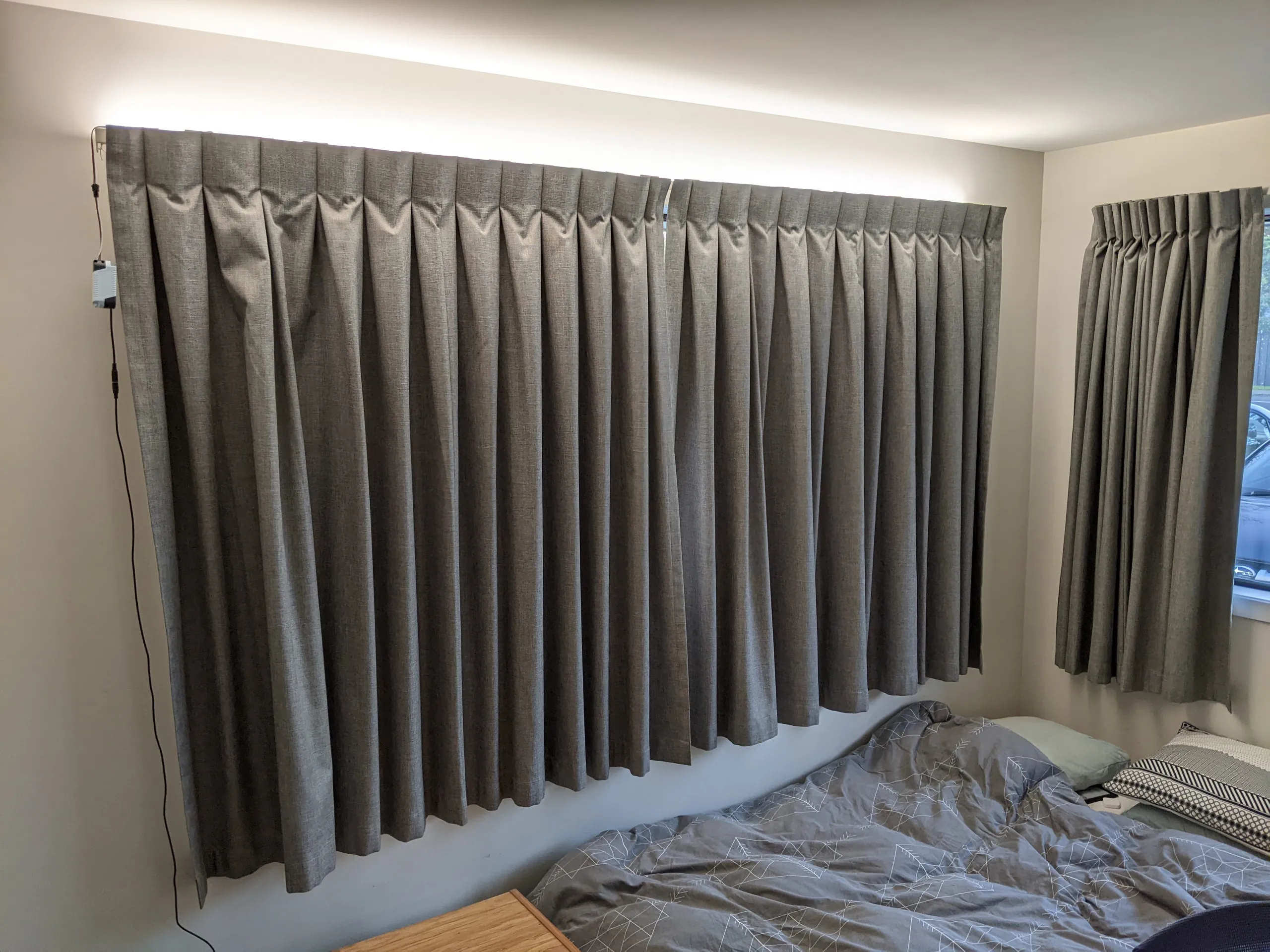
The result
It’s simple and it works. Introducing my new ceiling light! I’m really impressed by the quality of the light. While it’s fun being able to generate rainbows from lights like the SK6812, there’s something really beautiful about a natural, bright, high-CRI white. I’ll be sticking to this kind of strip whenever I just want illumination, not decoration, from a lighting project.